Separate thin red controller lead
The video moves its terminal into a shared brown/red housing. The electrical function, polarity and cavity are not established. Do not equate it with the throttle’s single-wire branch.
See 19:26, before the transferRevision 1 · 4 October 2026
A connector guide for the ZJLY08-BX-07 on the Venom E-Madix 48 V electric ATV.
Use the diagrams, wire groups and video timestamps to identify each branch, then record what you actually find on your machine.
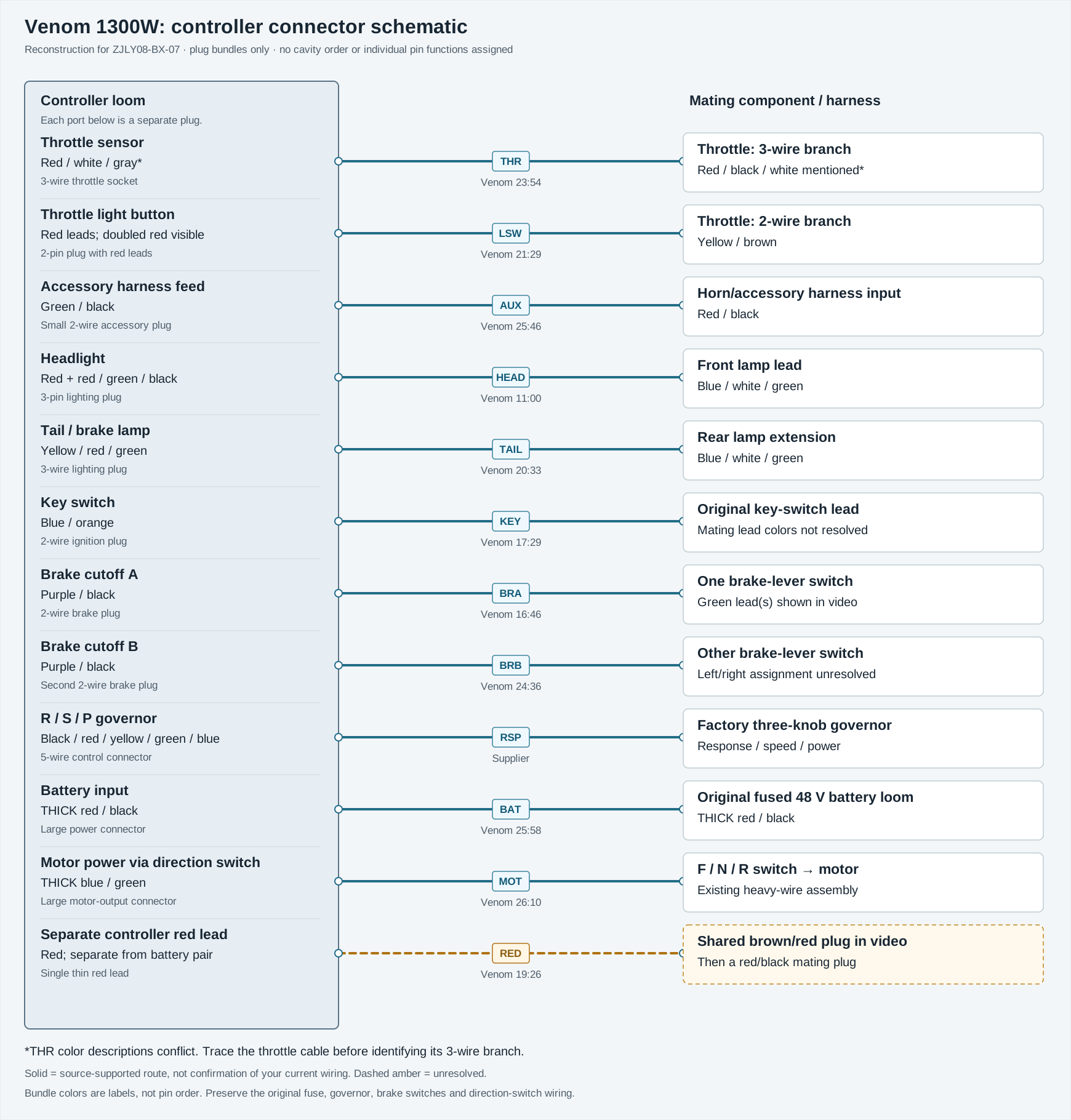
Connector reconstruction. These are wire-bundle routes, not an OEM electrical schematic or a verified pin-by-pin wiring diagram. A supported route still needs to be matched to the physical harness.
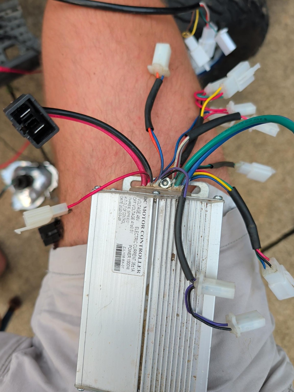
Use the markings on your own controller to establish the variant.
All five values above are transcribed from the photographed controller label. They are markings, not measured performance. In particular, 35 A is not a fuse-sizing recommendation.
MotoQuadElec’s same-model listing describes a controller for a brushed motor, with a two-wire motor output and a separate reversing switch. It is not a generic three-phase BLDC controller.
Venom’s replacement listing names the E-Madix 1300W 48V Lithium ATV and 2020-onward models. That listing does not prove that every year or harness revision has the same pin arrangement.
The photographed unit says 35 ±1 A. The supplier’s title says 35 A while its description says 40 ±1 A. This reference keeps the photographed value; it does not resolve the supplier’s contradiction.
“1300 W” or a similar case is not enough to identify a replacement.
Select a route label for its evidence. Zoom to read the wire groups.
Drag to pan; pinch or use +/− to zoom. Tab to a route and press Enter for evidence. These diagrams do not specify connector face orientation, cavity numbering or internal controller connections.
The codes are labels used in this worksheet, not manufacturer connector numbers. Wire order in a list is not pin order.
| Circuit | Controller / loom side | Mating branch | Evidence and limits |
|---|---|---|---|
| THR Throttle sensor | Red / white / gray*3-wire throttle socket | Red / black / white mentioned*Throttle: 3-wire branch | Source-supported routeRead evidence and limitsThe destination is supported, but the color descriptions disagree: the supplier lists red/white/gray; Venom's captions mention red/white/brown at 21:37 and red/black/white at 24:13. Identify this branch by tracing the cable from the grip. No individual supply, ground or signal pin is assigned here. |
| LSW Throttle light button | Red leads; doubled red visible2-pin plug with red leads | Yellow / brownThrottle: 2-wire branch | Source-supported routeRead evidence and limitsVenom pairs yellow/brown with the red-wire plug at 21:29 and reconnects it at 25:09. The supplier describes three red/pink conductors in this lighting group. Keep the existing doubled conductor; do not recreate its internal splice from this drawing. |
| AUX Accessory harness feed | Green / blackSmall 2-wire accessory plug | Red / blackHorn/accessory harness input | Source-supported routeRead evidence and limitsVenom explicitly pairs green/black with red/black. The supplier identifies this controller output as 48 V accessories. This is a pack-voltage accessory circuit; connector cavity order is not documented here. |
| HEAD Headlight | Red + red / green / black3-pin lighting plug | Blue / white / greenFront lamp lead | Source-supported routeRead evidence and limitsVenom identifies this pair during removal at 11:00 and reassembly at 42:30. Two red conductors share a position; this is not a four-pin assignment. The reference photograph shows this distinctive group, but its existing mating cable has not been traced. The pictured pairing is not a verified example. |
| TAIL Tail / brake lamp | Yellow / red / green3-wire lighting plug | Blue / white / greenRear lamp extension | Source-supported routeRead evidence and limitsVenom describes the rear-light pairing at 20:33–20:51. Front and rear lamp-side colors can be the same, so identify them by cable destination and controller-side color group. |
| KEY Key switch | Blue / orange2-wire ignition plug | Mating lead colors not resolvedOriginal key-switch lead | Source-supported routeRead evidence and limitsBoth the supplier and Venom identify blue/orange as the ignition connection. The video refers to a green plug at the body and a square plug with orange at reassembly. Do not infer pin order from housing color. |
| BRA Brake cutoff A | Purple / black2-wire brake plug | Green lead(s) shown in videoOne brake-lever switch | Source-supported routeRead evidence and limitsThere are two purple/black cutoff connectors. The video does not establish which is left and which is right. Retain both brake-switch circuits; this drawing does not specify their switch logic. |
| BRB Brake cutoff B | Purple / blackSecond 2-wire brake plug | Left/right assignment unresolvedOther brake-lever switch | Source-supported routeRead evidence and limitsThe second purple/black pair connects to the other brake-lever switch. The exact mating lead colors and left/right assignment need tracing on this machine. |
| RSP R / S / P governor | Black / red / yellow / green / blue5-wire control connector | Response / speed / powerFactory three-knob governor | Source-supported routeRead evidence and limitsThe model-specific supplier assigns this five-wire group to the three potentiometers. Count populated wires rather than assuming every cavity is occupied. Individual potentiometer terminals are not mapped. |
| BAT Battery input | THICK red / blackLarge power connector | THICK red / blackOriginal fused 48 V battery loom | Source-supported routeRead evidence and limitsThis is the main battery input, distinguishable by its thick conductors and large connector. Preserve the original battery box, fuse and charging arrangement. |
| MOT Motor power via direction switch | THICK blue / greenLarge motor-output connector | Existing heavy-wire assemblyF / N / R switch → motor | Source-supported routeRead evidence and limitsVenom connects this pair to the gear-selector harness; the supplier agrees. The selector's screw-terminal arrangement and internal reversing contacts are not established. Keep its original heavy-wire assembly intact. |
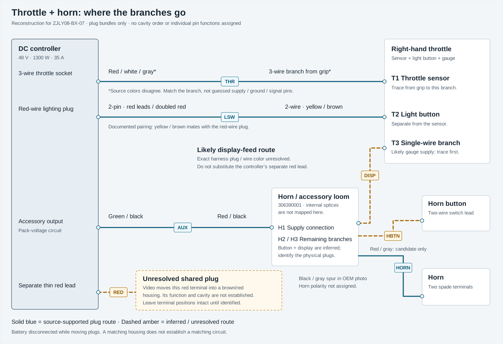
| RED Separate controller red lead | Red; separate from battery pairSingle thin red lead | Then a red/black mating plugShared brown/red plug in video | UnresolvedRead evidence and limitsAt 19:26 the housing remains with the ATV; at 22:06 the controller's red terminal is removed from it, then reinserted at 22:54. Its circuit function and cavity are not identified. This is not evidence that it should connect to the throttle's single-wire display lead. Do not depin or bridge it using this reconstruction. |
| DISP Throttle's third / display branch | Exact plug and wire color unresolvedAccessory harness branch — inferred | Likely battery-indicator feedThrottle: single-wire branch | InferredRead evidence and limitsThe OEM throttle photograph shows a third, single-wire connector. Venom describes an additional throttle power connection and says the accessory harness serves the display. The likely destination is that harness, but the transcript never establishes the exact mating plug or cavity. Keep this route dashed until traced. |
| HBTN Horn button branch | Red / gray is a candidate pairHorn/accessory loom — inferred | Trace the button cableHandlebar horn button | InferredRead evidence and limitsOEM photos show a two-wire horn button and an accessory loom with red/gray and red/black branches. Red/gray is a plausible switch branch, not a verified assignment. With battery and both ends disconnected, continuity tracing can identify which branch reaches the horn terminal and which reaches the supply splice. |
| HORN Horn itself | Black / gray in OEM photographTwo spade leads on accessory loom | Polarity not assignedTwo terminals on horn | Source-supported routeRead evidence and limitsThe horn has two spade connections. The multiple white plugs belong to the accessory loom. The photo establishes the physical two-wire spur, not the horn's terminal polarity or every internal splice. |
Reference photos show hardware and wire entries. They do not validate the existing pairings.
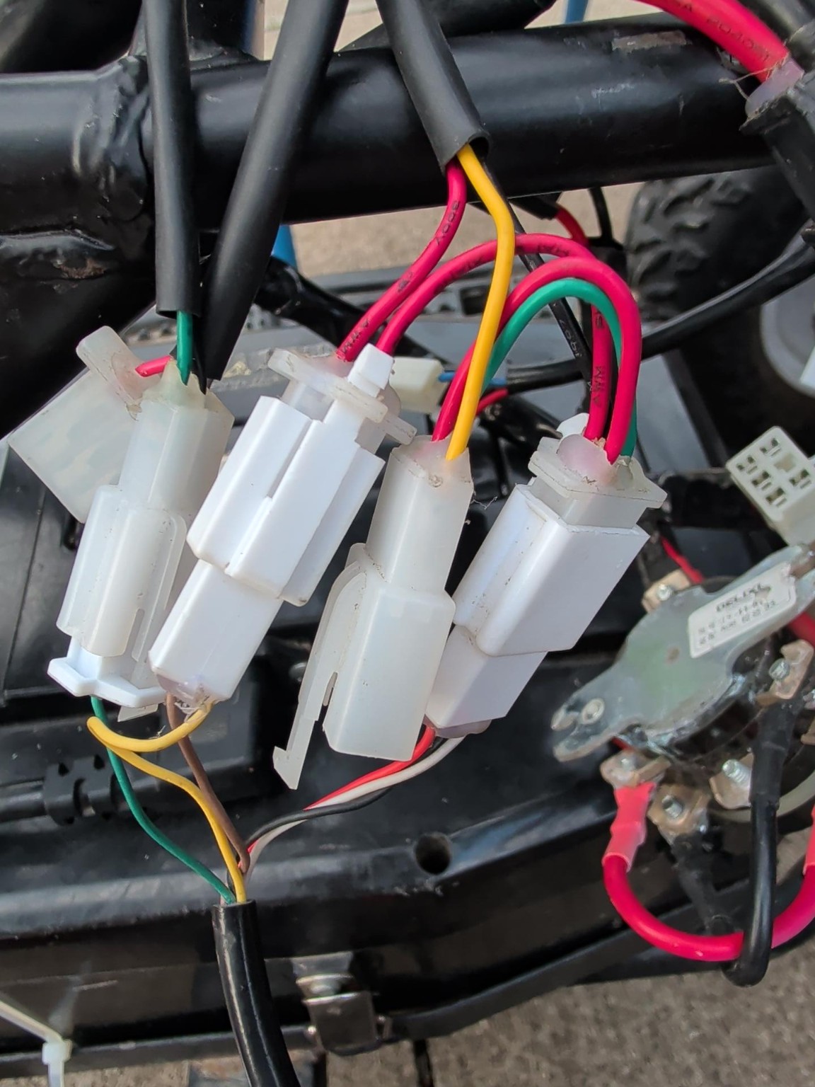
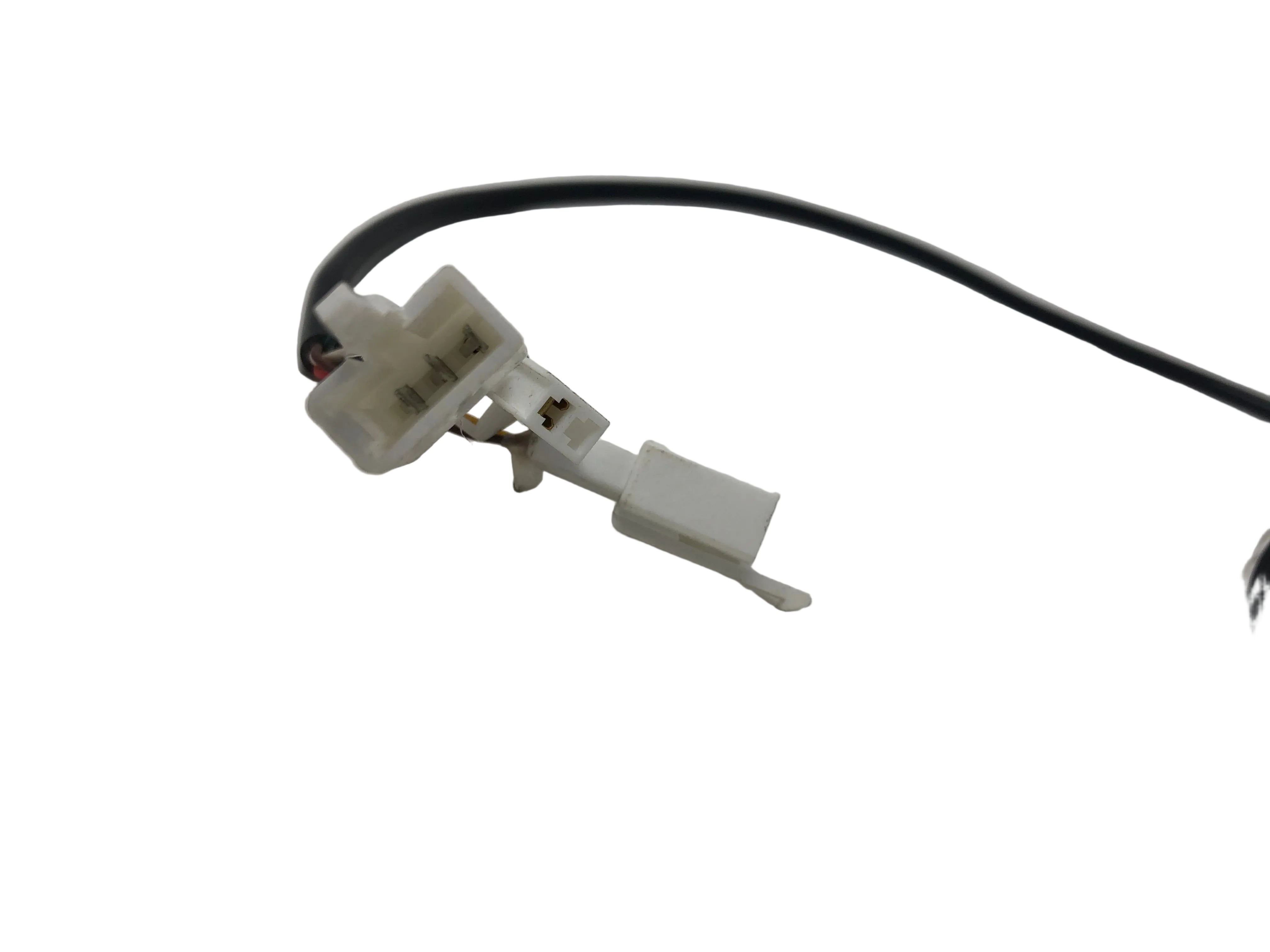
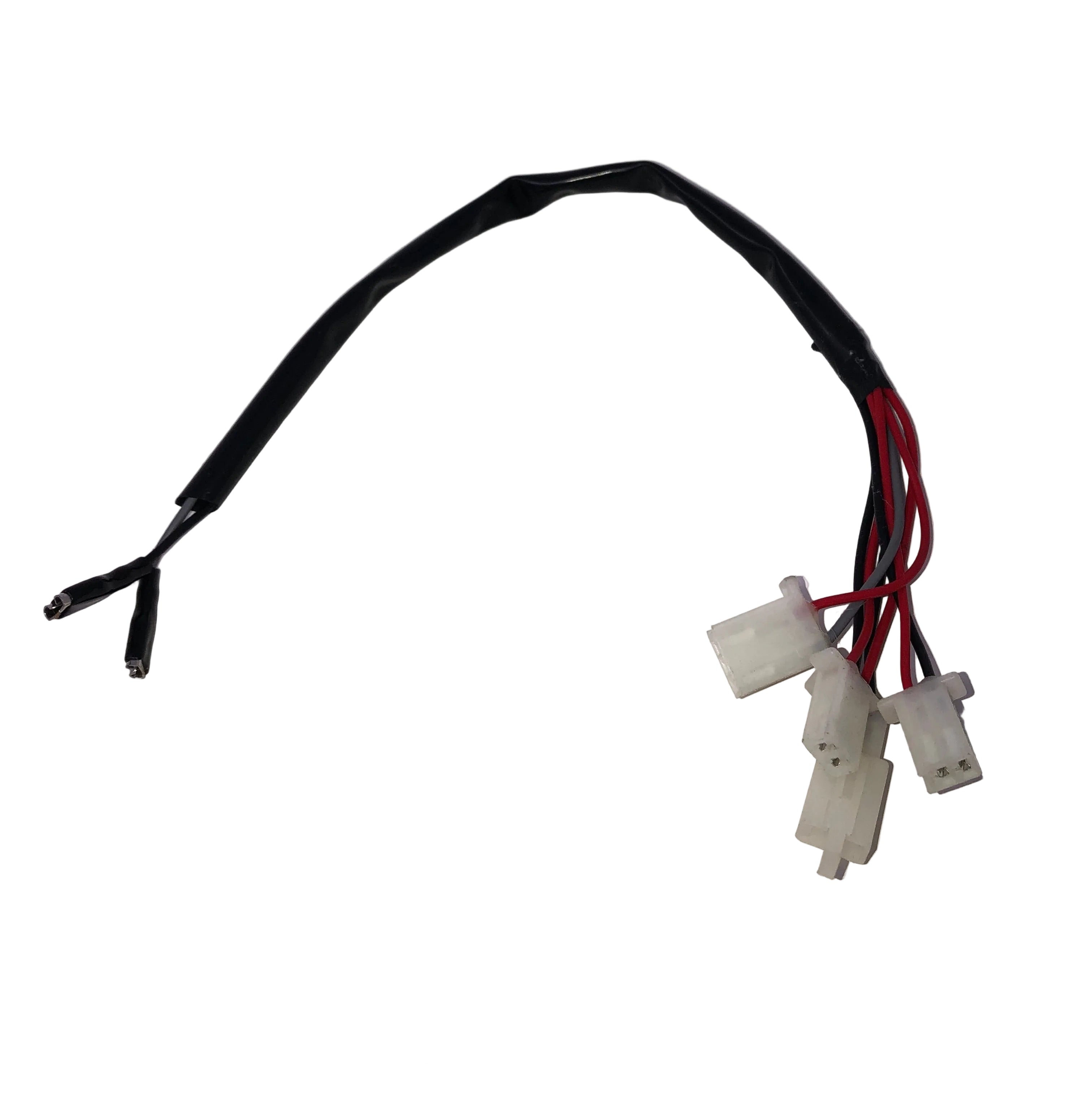
The distinctive double-red / green / black group is identified by the video as the headlight connection. A red/black/white mating cable in a photograph does not prove that it belongs there. Trace the cable to its component before making that assignment. This photo is not a known-good wiring example.
How to Change the Controller on the Venom 1300w E-Madix Electric ATV, by Venom Motorsports Canada/USA, published 17 October 2023.
These links open the relevant moments in the original video. Notes are paraphrases based on its automatic captions and earlier storyboard inspection. Full-resolution footage was not reviewed for every connection; colors and terminal positions must still be checked on the hardware.
Doubled red / green / black paired with blue / green / white.
The loom serves horn, lights and display; an unused connector is shown.
Two purple / black connections serve the brake switches.
Blue / orange is identified as the ignition connection.
The shared brown/red housing stays with the machine. Function unresolved.
Yellow / red / green paired with the rear-light extension.
Yellow / brown mates with the red-wire lighting plug.
Removal and reinsertion start here; this reference does not assign a cavity.
Reconnection; caption colors conflict with the supplier’s list.
Both brake-switch branches are reconnected.
The separate lighting branch is reconnected.
Green / black paired with the accessory loom’s red / black.
The large red / black power connection.
The heavy motor-output route is reconnected.
A second reference for the front-light connection.
The video is linked at its source. This page does not redistribute the video or its full transcript.
Leave these assignments open until there is direct evidence.
The video moves its terminal into a shared brown/red housing. The electrical function, polarity and cavity are not established. Do not equate it with the throttle’s single-wire branch.
See 19:26, before the transferThe display-feed branch and a possible red/gray horn-button branch are inferred. The exact plugs and accessory-loom splices remain unverified.
No connector cavity order, throttle sensor pin functions, horn terminal polarity or direction-switch screw-terminal wiring is assigned. The two brake plugs are not assigned left/right.
The supplier mentions a separate charge input, but that route is not established for the photographed unit. OEM accessory harnesses vary, and the video shows an unused connector. A loose plug does not necessarily need a mate.
Fill this in on screen or print it blank. Entries stay in this open page; print to keep a copy.
Revision 1 · 4 October 2026 · Connector reconstruction, not a pinout.
https://yaco.me/venom-controller/
Battery and charger disconnected. Photograph both sides before moving plugs. Retain the factory safety circuits. Record the wire-entry view or mating-face view and latch direction; those views are mirror images.
Trace a cable to its component before assigning a function. If using continuity, isolate both ends from power and electronics and verify that the circuit is de-energized. This worksheet does not call for live probing or bypassing controls.
| Reference circuit | Wire colors, cavity count, latch view, traced destination and photo ID |
|---|---|
| THR · Throttle sensorRed / white / gray* Source-supported route | |
| LSW · Throttle light buttonRed leads; doubled red visible Source-supported route | |
| AUX · Accessory harness feedGreen / black Source-supported route | |
| HEAD · HeadlightRed + red / green / black Source-supported route | |
| TAIL · Tail / brake lampYellow / red / green Source-supported route | |
| KEY · Key switchBlue / orange Source-supported route | |
| BRA · Brake cutoff APurple / black Source-supported route | |
| BRB · Brake cutoff BPurple / black Source-supported route | |
| RSP · R / S / P governorBlack / red / yellow / green / blue Source-supported route | |
| BAT · Battery inputTHICK red / black Source-supported route | |
| MOT · Motor power via direction switchTHICK blue / green Source-supported route | |
| RED · Separate controller red leadRed; separate from battery pair Unresolved | |
| DISP · Throttle's third / display branchExact plug and wire color unresolved Inferred | |
| HBTN · Horn button branchRed / gray is a candidate pair Inferred | |
| HORN · Horn itselfBlack / gray in OEM photograph Source-supported route |
Next evidence to collect: a readable label, both connector faces with orientation, wire-entry colors, and the traced component at the other end. Record voltage only with a clearly identified reference point and an appropriate safe test method. Preserve uncertain assignments as uncertain.
Evidence checked against the public listings and local reference material on 4 October 2026.
The original text, diagrams and connector dataset on this page are available under CC BY 4.0. Credit “Venom 1300W controller wiring worksheet, Anthony Yacobucci,” link to this page, and identify any changes. Carry the uncertainty labels and source links into derivative wiring references.
Photographs, the Venom video and third-party source material are excluded from that license and remain with their respective rights holders. This is an independent reference, not a Venom publication or approval.
Revision 1: publishes the source-based reconstruction, distinguishes the headlight connector from the throttle, and leaves the single red lead, display feed, horn-button branch and pin order unresolved.